


info@happytechnovation.com
Cad Automation and Customization services at Happy Technovation

Cad Automation and Customization

We offer CAD automation and customization services to streamline design processes, improve efficiency, and enhance project quality for our clients.

CAD Automation and Customization

We provide comprehensive CAD automation and customization services designed to optimize design workflows and enhance productivity. Our expert team analyzes client needs and implements tailored solutions, including automated scripts and specialized tools, to eliminate repetitive tasks and reduce errors. This allows our clients to focus on creative design rather than manual input, ultimately leading to faster project completion times and improved overall quality. By integrating innovative CAD technologies, we empower organizations to adapt to changing demands and stay ahead of the competition. Our commitment to customization ensures that each solution is perfectly aligned with client requirements and expectations.

We provide step by step interactive solution from basic programming to professional Add-in / Plug-in & Applications development. 

Our Services includes Automation & customization of various CAD tools like CATIA V5 and 3DX, NX, CREO, Solid works, Solid Edge, AutoCAD.

Automate & customize using different programming languages like C++ , CAA, C#, NET, VB.NET, JAVA & PYTHON.

USE CASES

Use case illustration
Complete Vehicle Lamp Regulations – ECE R48 - SAE
Problem Statement: Checking position, visibility, and non-visibility for all vehicle lamp variants under ECE R48 and SAE regulations is time-consuming and complex.
Solution: Automate the verification process for position, visibility, and non-visibility across all lamp variants. Ensure compliance with ECE R48 and SAE standards efficiently.
Efficiency Improvement: Reduces verification time by up to 80%, streamlining the process and ensuring consistent compliance across all variants.

Head Impact Analysis - ECE R21, FMVSS 201 , NCAP
Problem Statement: Head impact analysis in CAD for ECE R21, FMVSS 201, and NCAP standards is time-consuming and manually intensive, involving complex simulations and evaluations.
Solution: Implement CAD automation to streamline head impact analysis. Integrate automated simulations and evaluations to meet ECE R21, FMVSS 201, and NCAP requirements.
Efficiency Improvement: Reduces analysis time by up to 70%, accelerates compliance testing, and minimizes manual effort.
Use case illustration

Use case illustration
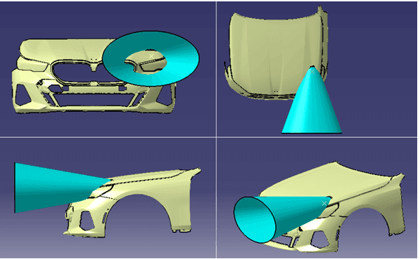
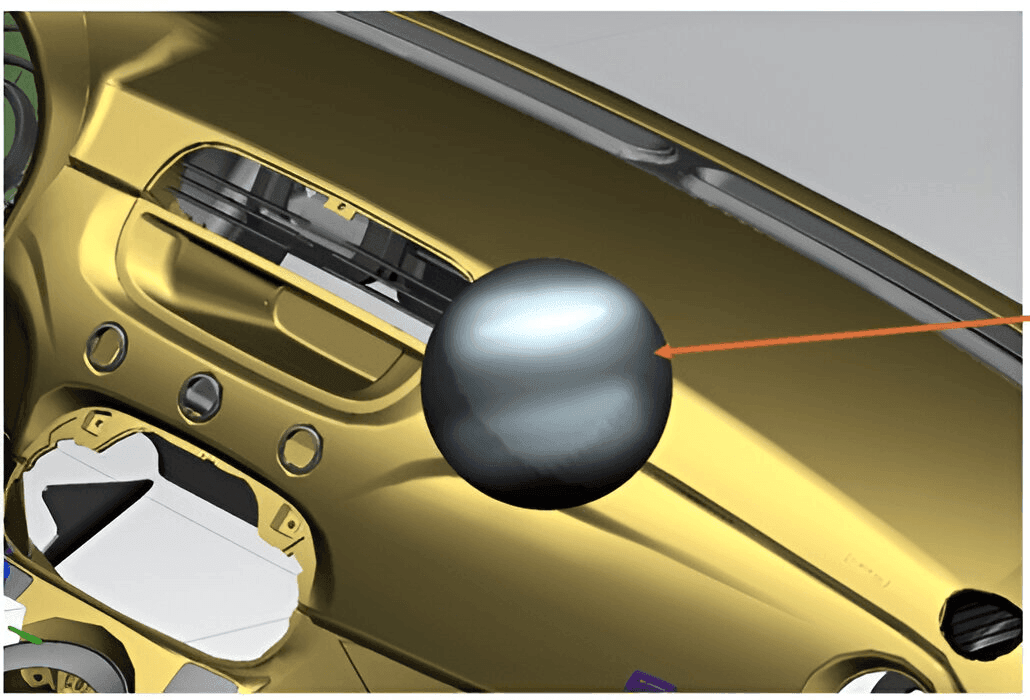
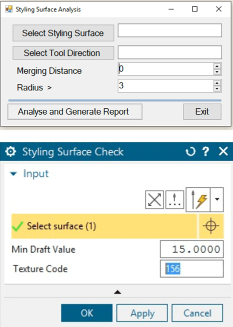
Styling Surface Analysis
Problem Statement: Designers face challenges in verifying styling surfaces against R61 regulations, curvature requirements, and tooling feasibility during each design phase. The process is time-consuming and complex.
Solution: Automate the verification of styling surfaces for R61 compliance, curvature analysis, and tooling feasibility. Streamline checks with integrated tools.
Efficiency Improvement: Reduces verification time by up to 60%, accelerates design iterations, and simplifies compliance and feasibility assessments.

A to B Surface Creation
Problem Statement: During the design phase, creating a close body from surfaces and generating A-to-B surfaces is time-consuming and labor-intensive.
Solution: Implement automation tools to streamline the process of creating close bodies and A-to-B surfaces. Enhance efficiency with integrated CAD functionalities.
Efficiency Improvement: Cuts creation time by up to 50%, allowing designers to focus on other critical tasks and speeding up the overall design process.
Use case illustration

Use case illustration
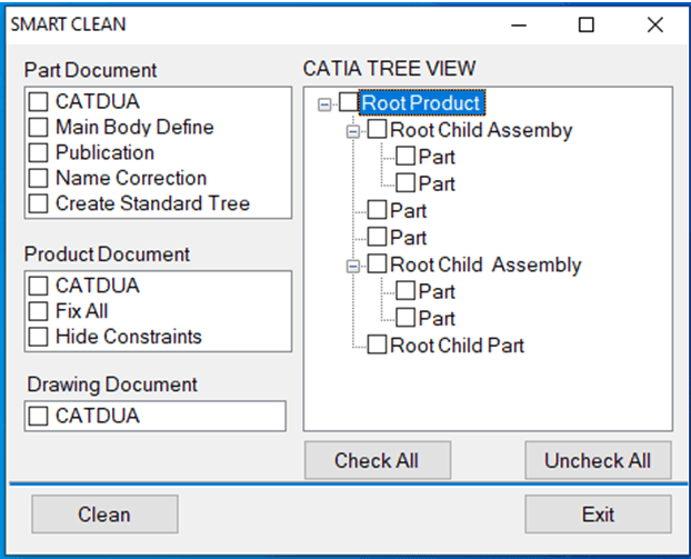
Smart Clean
Problem Statement: Design release activities involve repetitive tasks such as CATDDUA, Fix All, and deleting useless elements for each individual part. These activities are time-consuming and do not add direct value to the engineering process.
Solution: Automate repetitive design release tasks, including CATDDUA, Fix All, and element cleanup, across multiple parts simultaneously.
Efficiency Improvement: Reduces time spent on repetitive tasks by up to 70%, freeing designers to focus on value-added engineering activities and accelerating the design release process.

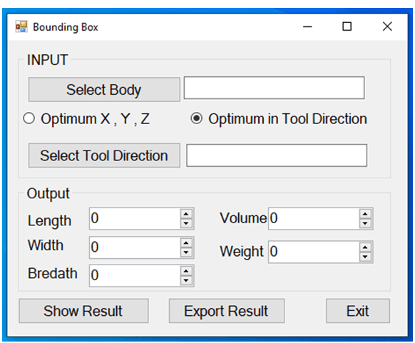
Optimum Bounding Box
Problem Statement: In the Concept, Design, and Tooling phases, designers spend hours creating bounding boxes to determine the optimal size of parts for securing tool blocks from suppliers.
Solution: Automate the creation of bounding boxes and the extraction of length, breadth, and width based on tool direction.
Efficiency Improvement: Reduces the time required for bounding box creation by up to 80%, streamlining the process of securing tool blocks and accelerating the overall design phase.
Use case illustration

Use case illustration
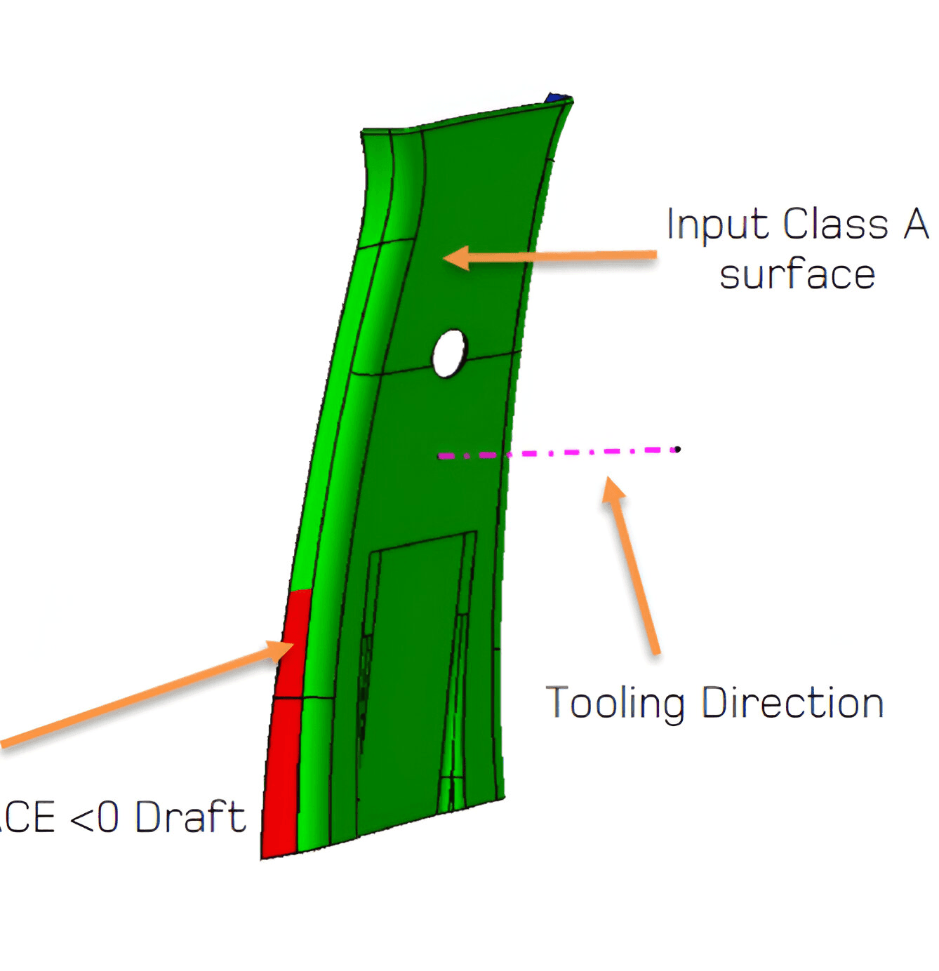
Draft analysis for style surface
Problem Statement: Performing draft analysis for surfaces manually is time-consuming and lacks clear visual indicators for results.
Solution: Automate draft analysis for surfaces with color-coded results indicating red, yellow, and green zones based on input parameters.
Efficiency Improvement: Reduces analysis time by up to 50%, provides clear visual feedback, and simplifies the process of identifying draft issues.

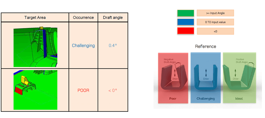
Draft analysis for part in main tool
Problem Statement: Highlighting draft angles and ensuring easy part removal from the tool is complex, and creating editable PowerPoint reports is time-consuming.
Solution: Automate draft angle highlighting in CATIA, ensure easy part removal, and generate editable PowerPoint reports.
Efficiency Improvement: Cuts analysis time by 60%, simplifies part removal, and speeds up report creation.
Use case illustration

Use case illustration
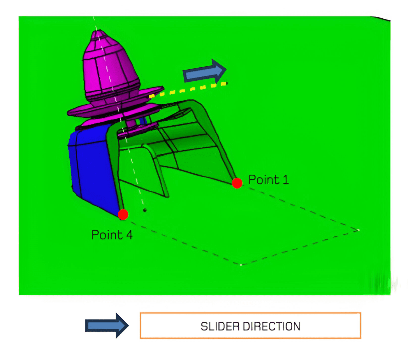
Draft analysis in slider direction
Problem Statement: Checking lifter travel and providing feedback from inputs using CATIA’s draft analysis tool is manual and lacks color-coded results.
Solution: Automate the lifter travel check and feedback process by directly integrating with CATIA's draft analysis tool, using color-coded results.
Efficiency Improvement: Streamlines the check process, provides clear color-coded feedback, and reduces manual effort.

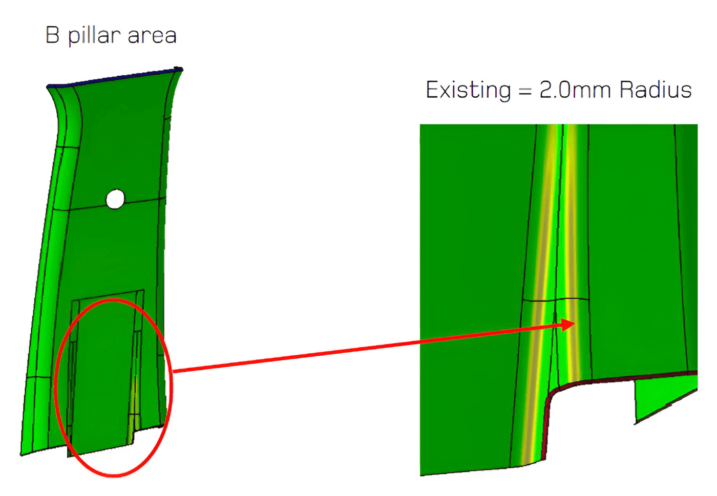
Curvature analysis
Problem Statement: Highlighting curvature with the minimum baseline value for head impact zones and optimizing part geometry is manual and complex.
Solution: Automate the highlighting of curvature with the required minimum radius using CATIA's Curvature Analysis tool in the Part Design Workbench.
Efficiency Improvement: Simplifies curvature analysis, ensures accurate optimization, and reduces manual effort.
Use case illustration

Use case illustration
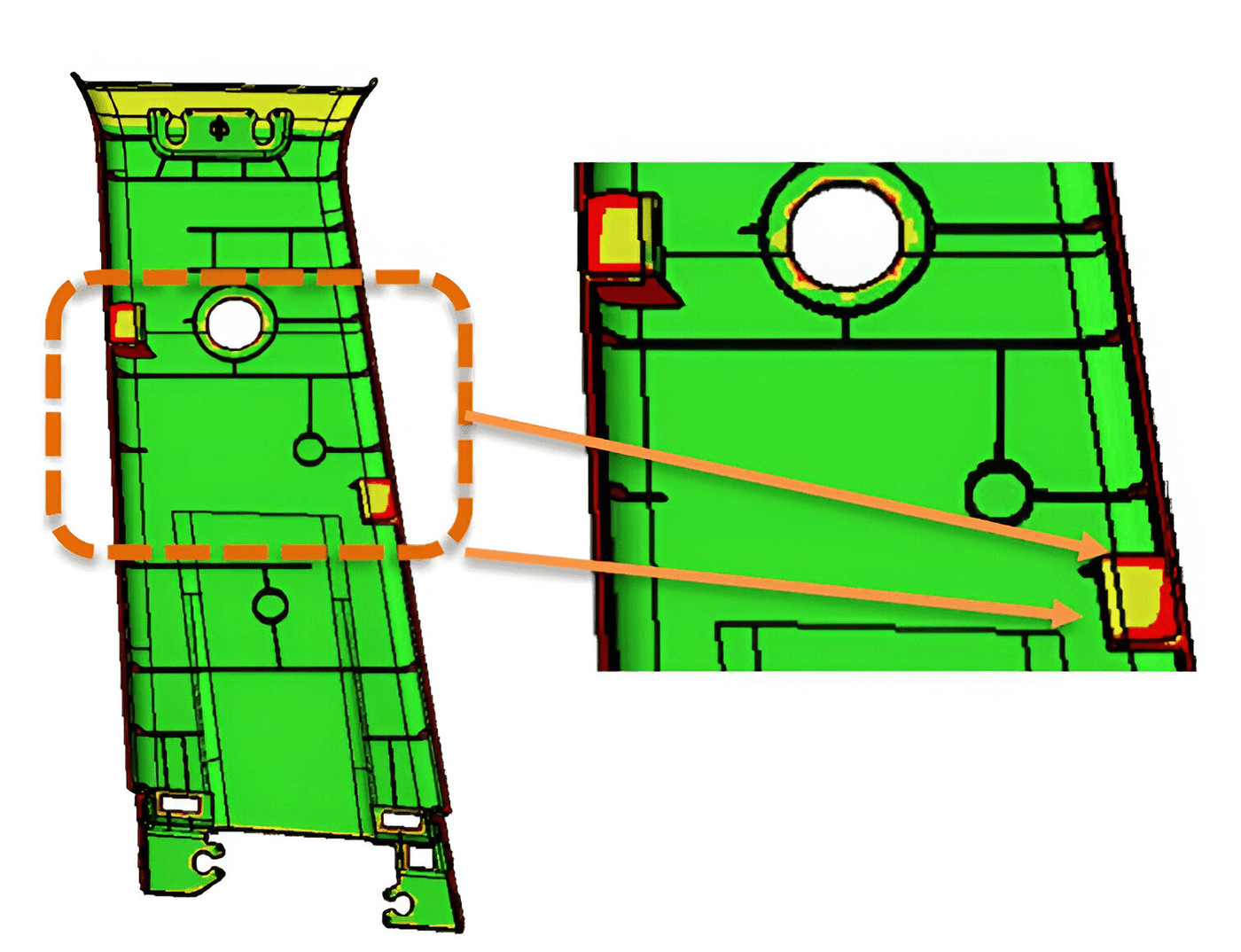
Weak plastic condition check
Problem Statement: Identifying and highlighting areas with thickness less than the minimum input value of 0.8 mm to avoid weak plastic areas is manual and lacks clear visual indicators.
Solution: Automate the highlighting of affected areas with color-coded feedback where the thickness is below the 0.8 mm minimum input value.
Efficiency Improvement: Provides clear, color-coded visual feedback, ensuring areas meet minimum thickness requirements and reducing manual inspection.

Wall thickness analysis
Problem Statement: Highlighting wall thickness variations and ensuring they meet the minimum required values is manual and lacks clear visual feedback.
Solution: Automate the highlighting of wall thickness variations using color-coded indicators if below the permitted minimum value, directly integrating with CATIA's Wall Thickness tool in the Part Design Workbench.
Efficiency Improvement: Provides clear, color-coded feedback on wall thickness, ensuring compliance and reducing manual effort.
Use case illustration

Use case illustration
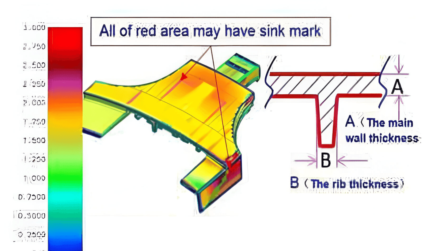
Sink mark Analysis
Problem Statement: Identifying and highlighting areas affected by insufficient values to avoid sink marks is manual and lacks visual clarity.
Solution: Automate the highlighting of affected areas with color-coded values compared to the minimum input value, if below the permitted threshold.
Efficiency Improvement: Provides clear, color-coded visual feedback, ensuring areas meet minimum requirements and reducing manual effort.

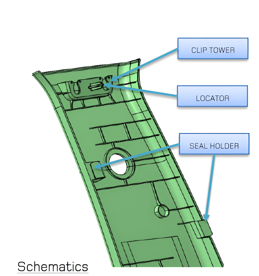
B-side fixation study and comparison with standard feature
Problem Statement: Comparing standard features and generating reports with color-coded results is manual and time-consuming.
Solution: Automate the comparison of standard features and generate editable PowerPoint reports with color-coded results.
Efficiency Improvement: Speeds up comparison and report generation, ensuring accurate and easily editable documentation.
Use case illustration

Use case illustration
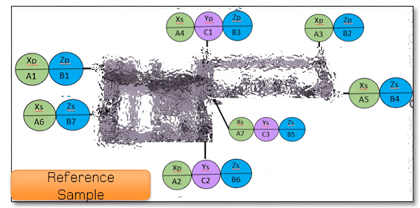
Locator RPS clearance check
Problem Statement: Comparing standard features and generating reports with color-coded results is manual and time-consuming.
Solution: Automate the comparison of standard features and generate editable PowerPoint reports with color-coded results.
Efficiency Improvement: Speeds up comparison and report generation, ensuring accurate and easily editable documentation.

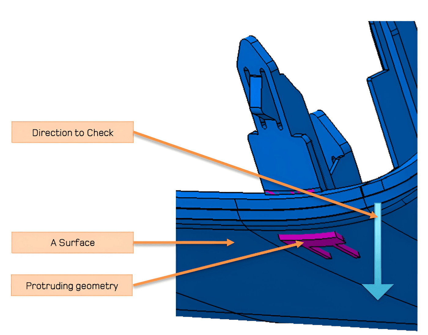
Identify the feature integration issue from A-side
Problem Statement: Task: Identify protruding geometry from the A surface in the input direction.
Solution: Automate the detection of protruding geometry relative to the A surface and highlight the areas of concern.
Efficiency Improvement: Integrate the detection tool into the design workflow to quickly identify and address protrusions, reducing manual checks.
Use case illustration

Use case illustration
Clean structure analysis
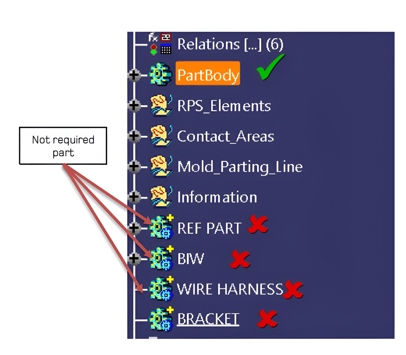
Problem Statement: Task: Identify unlinked part bodies to keep the history tree clean.
Solution: Automate the detection of unlinked part bodies and provide a report to clean the history tree.
Efficiency Improvement: Integrate the tool into the design workflow to maintain a clean history tree with minimal manual intervention.

DMU check
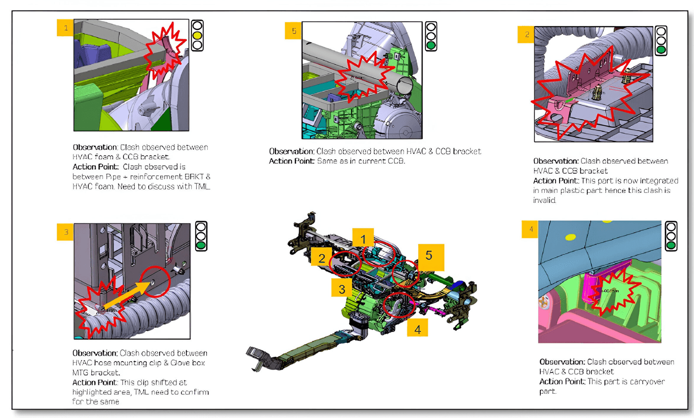
Problem Statement: Identify and highlight clearance and interference points from clash analysis in CATIA for a presentation.
Solution: Extract clash analysis results, capture screenshots, and annotate interference and clearance areas in a PowerPoint presentation.
Efficiency Improvement: Automate result extraction and screenshot capture using CATIA macros to save time and enhance accuracy.
Use case illustration

Use case illustration
Feature Integration error analysis
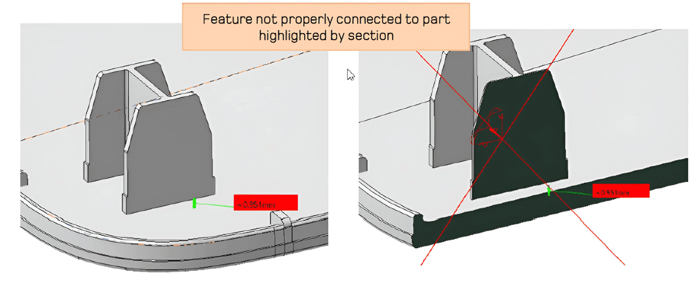
Problem Statement: Task: Ensure there are no gaps between B-side features and the base close volume in a plastic component. Highlight any gaps in a PowerPoint presentation, showing their locations.
Solution: Create an automated system to check for gaps between B-side features and the base volume. Highlight any gaps with color codes or shapes and include this information in a PowerPoint slide.
Efficiency Improvement: Integrate the gap detection and highlighting into the design workflow, automating the PowerPoint report generation to reduce manual inspection and ensure quick identification of issues.

Loading study
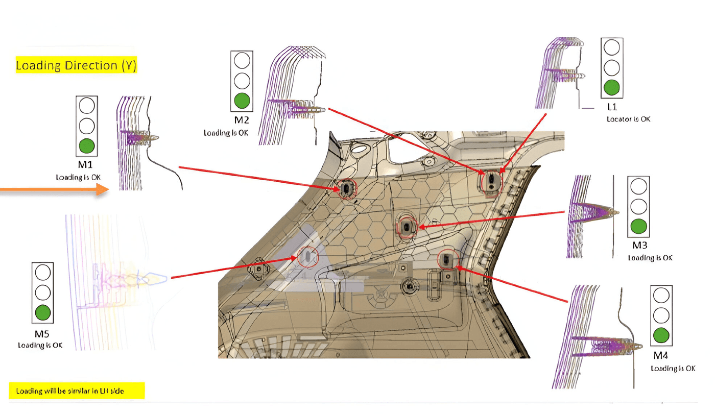
Problem Statement: Validate and highlight the engagement of locators before clip fixation along the assembly's defined axis, ensuring compliance with the required loading direction for a plastic component.
Solution: Automate the validation process to check locator engagement prior to clip fixation, using color codes to indicate engagement status, loading clearance, locator clearance, and any clashes with the environment.
Efficiency Improvement: Integrate a script that automatically performs these validations in the CAD software, applying color codes and generating a report to streamline the review process and reduce human error.
Use case illustration

Use case illustration
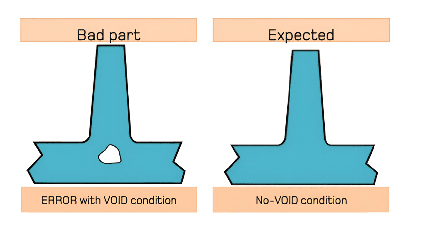
Void Analysis
Problem Statement: Automate void space detection and highlight them in a PowerPoint presentation with color codes or curves.
Solution: Create a system to detect voids, highlight them, and generate annotated PowerPoint slides.
Efficiency Improvement: Integrate detection and highlighting into a streamlined workflow for faster, more accurate results.

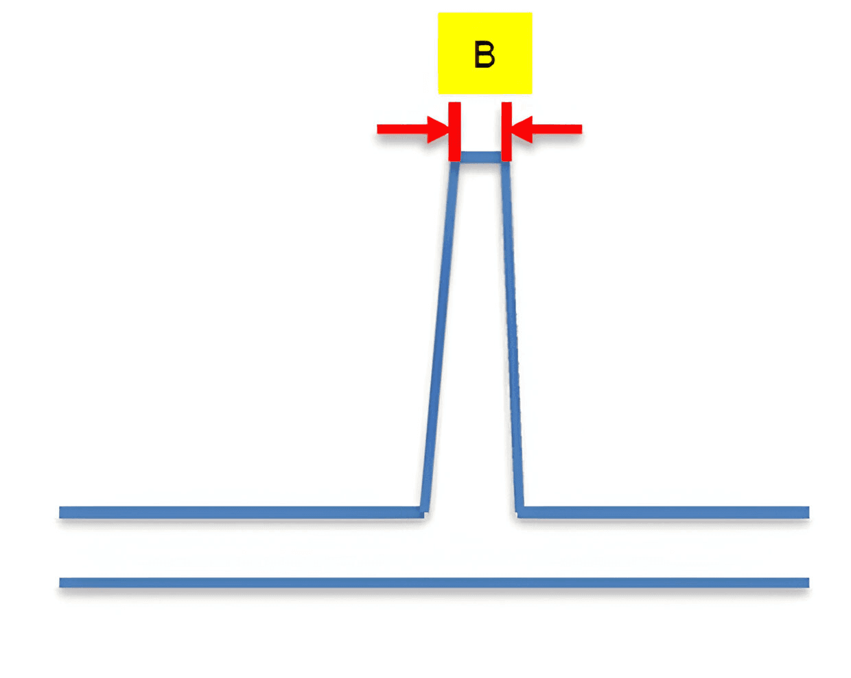
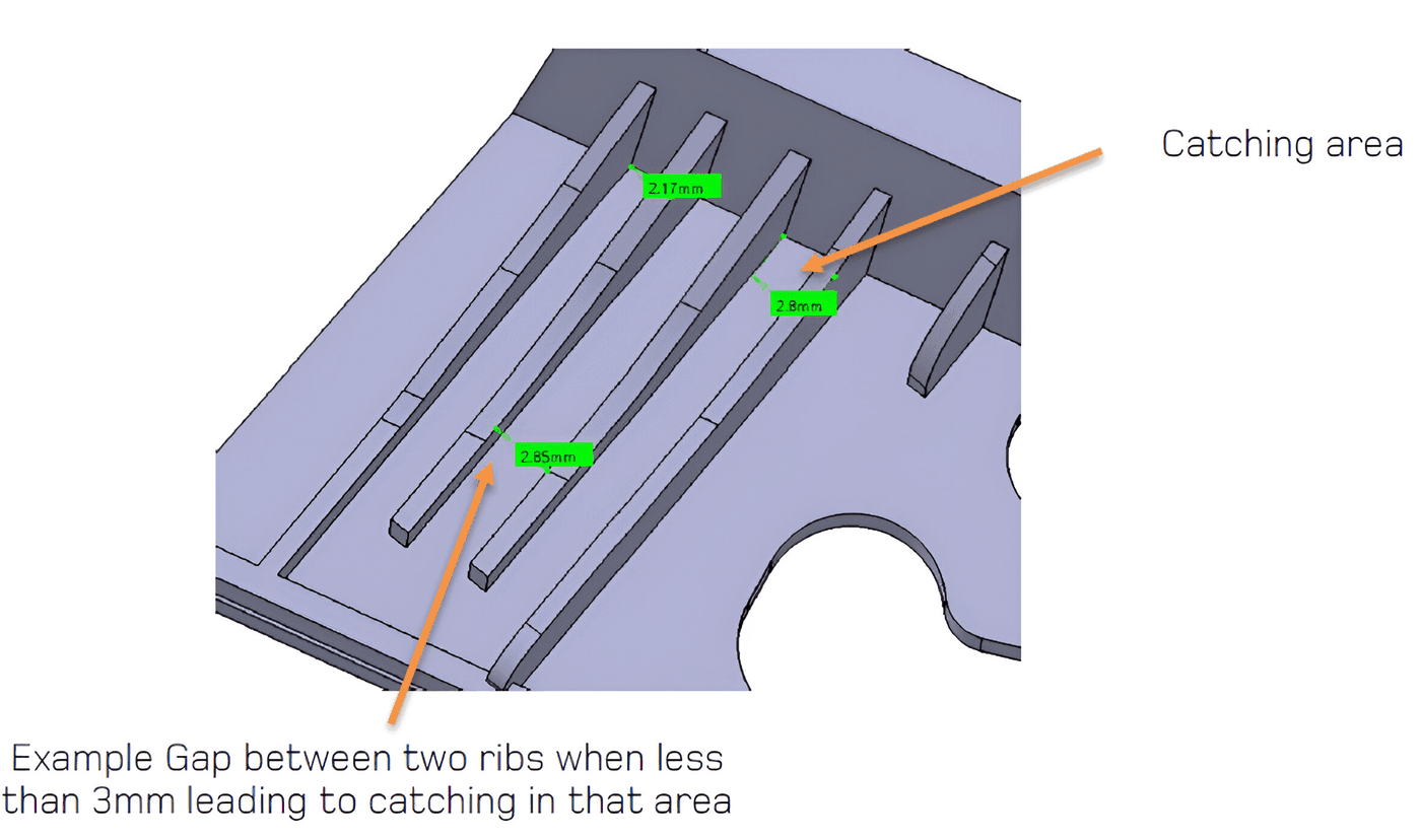
Weak steel analysis
Problem Statement: Identifying and highlighting gaps less than the minimum 3 mm width to prevent catching issues is manual and lacks clear visual feedback.
Solution: Automate the highlighting of gaps less than 3 mm with color-coded output to indicate areas that need attention.
Efficiency Improvement: Provides clear, color-coded feedback on gap areas, reducing manual inspection and ensuring design accuracy.
Use case illustration

Use case illustration
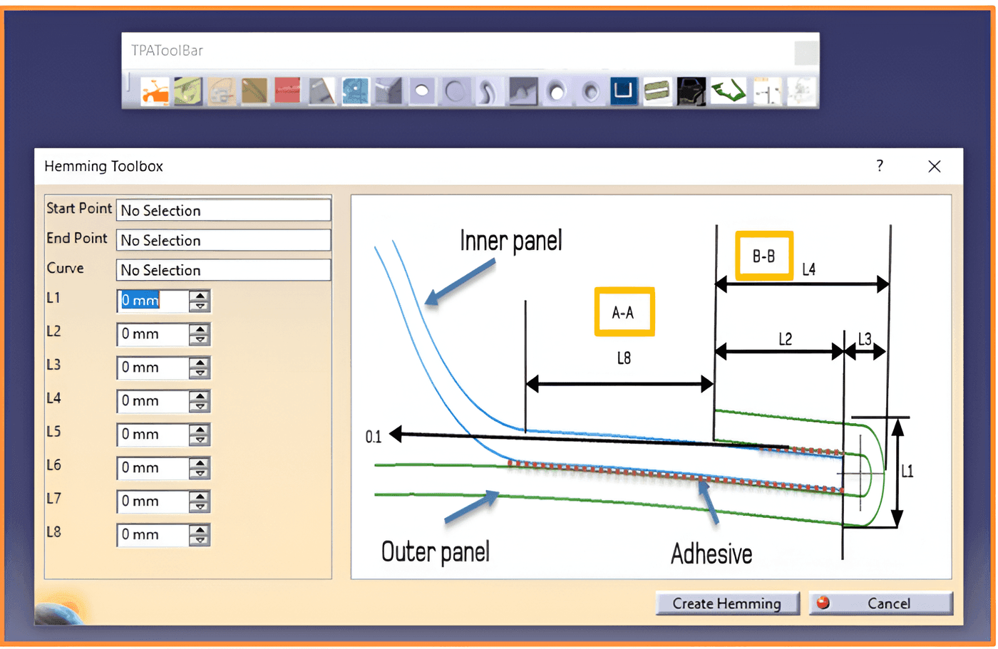
Creation of Hemming Zone
Problem Statement: In the Body-in-White (BIW) assembly process, creating a precise hemming zone is critical for ensuring proper joint sealing and aesthetic finish, particularly in areas like door edges and hoods.
Solution: By implementing advanced robotic hemming commands and optimizing tool paths, the hemming process can be made more accurate and consistent.
Efficiency Improvement: This approach reduces manual rework, lowers cycle times, and improves overall production throughput by up to 20%, while simultaneously enhancing the quality of the hemming process and minimizing material waste.

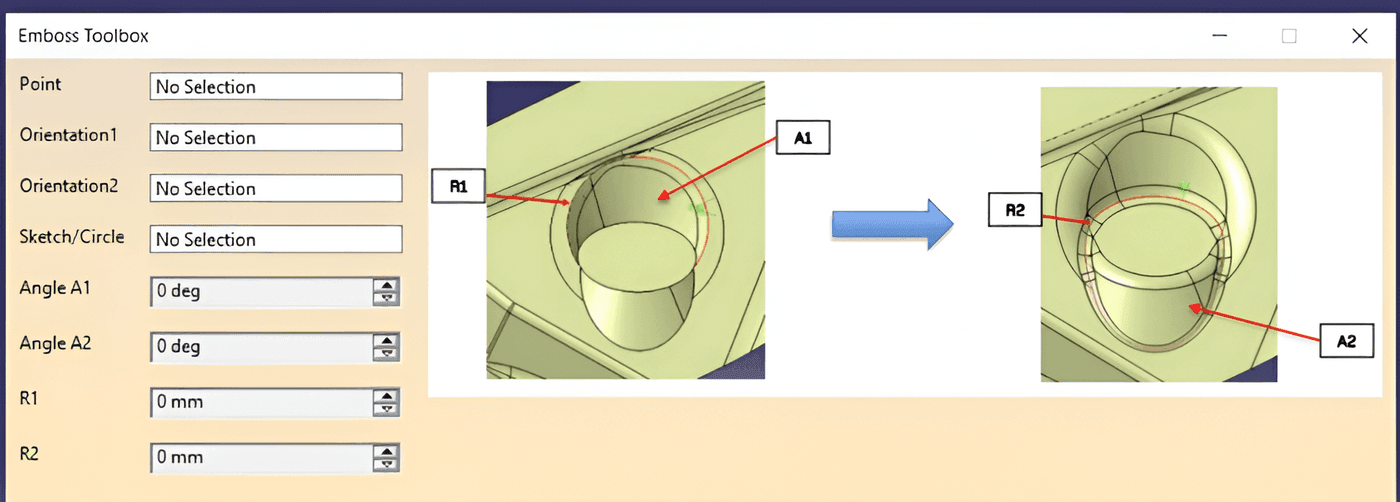
Creation Of Emboss/Diabolo
Problem Statement: Inconsistent emboss or diabolo formations in BIW components lead to structural weakness, increased rework, and inefficiencies in production.
Solution:Using advanced CAD/CAM techniques, along with precise stamping and forming tools, allows for consistent creation of emboss or diabolo features with accurate depth and contour.
Efficiency Improvement: This automated approach improves production accuracy, reducing rework by up to 15%, and enhances the overall structural integrity of the components.
Use case illustration

Use case illustration
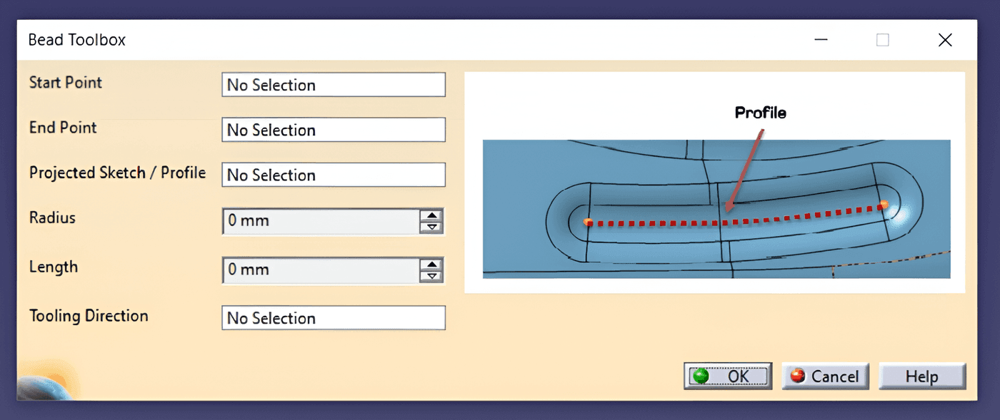
Creation Of Beads
Problem Statement: Inconsistent bead formation in BIW components can lead to reduced structural rigidity, increased rework, and prolonged production times.
Solution: Automating the bead creation process with advanced forming tools ensures consistent bead depth and shape, improving structural integrity and reducing defects.
Efficiency Improvement: This approach enhances production efficiency by up to 15%, reduces material waste, and lowers rework rates, leading to faster cycle times and better component quality.

Creation Of U Beads
Problem Statement: The creation of U beads is essential for strengthening panels and managing deformation during crashes.
Solution: By employing automated U bead forming techniques with precise control over the bead shape and depth, the process can ensure uniformity and improved strength across all parts, minimizing defects.
Efficiency Improvement: This automation reduces rework by 20%, enhances structural integrity, and shortens production cycle times, improving overall efficiency by approximately 15%.
Use case illustration

Use case illustration
Creation Of V Beads
Problem Statement: Inconsistent V bead formation in BIW components can lead to compromised rigidity and uneven stress distribution, resulting in weaker parts and increased rework.
Solution: Automating the V bead creation process with precision forming tools ensures consistent bead shape and depth, improving part rigidity and stress distribution.
Efficiency Improvement: This method reduces rework by 15%, increases production speed, and enhances component durability, leading to an overall efficiency improvement of up to 12%.

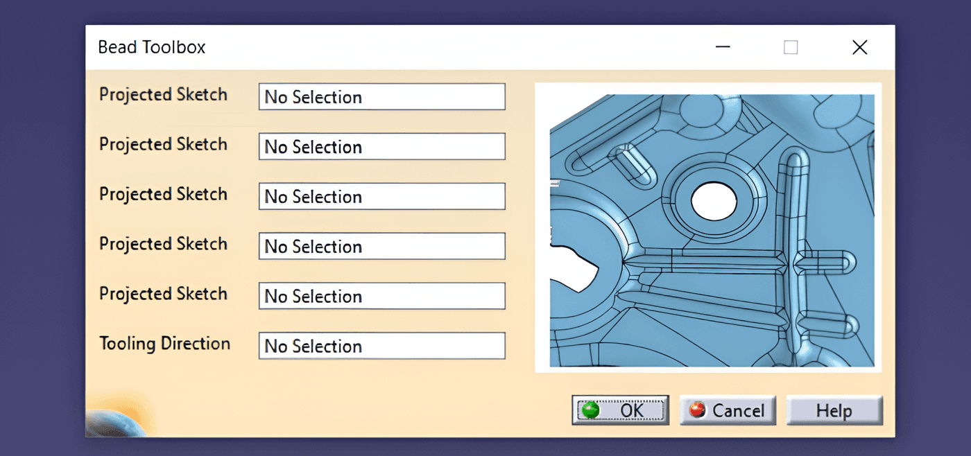
Creation Of Multi Beads
Problem Statement: Creating multi beads in BIW components is crucial for enhancing stiffness and structural integrity.
Solution: Using automated multi-bead forming tools with advanced control ensures uniform bead patterns and precise depths across multiple beads, enhancing component strength and reducing defects.
Efficiency Improvement: This approach boosts production efficiency by 18%, decreases rework, and shortens cycle times, while ensuring higher structural integrity and part quality.
Use case illustration

Use case illustration
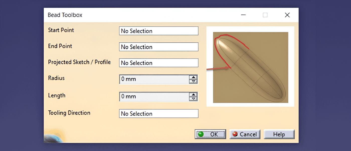
Creation Of Open Ended Beads
Problem Statement: Open-ended beads in BIW components are essential for enhancing stiffness without fully enclosed sections.
Solution: Automating the creation of open-ended beads with advanced forming tools ensures precise bead ends and uniformity, improving the component's stiffness and reducing defects.
Efficiency Improvement: This process enhances production efficiency by up to 15%, reduces material wastage, and lowers rework, leading to faster cycle times and better part quality.

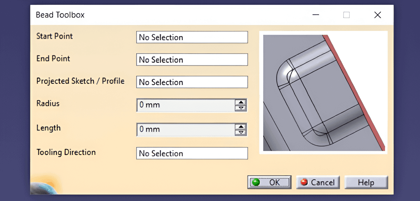
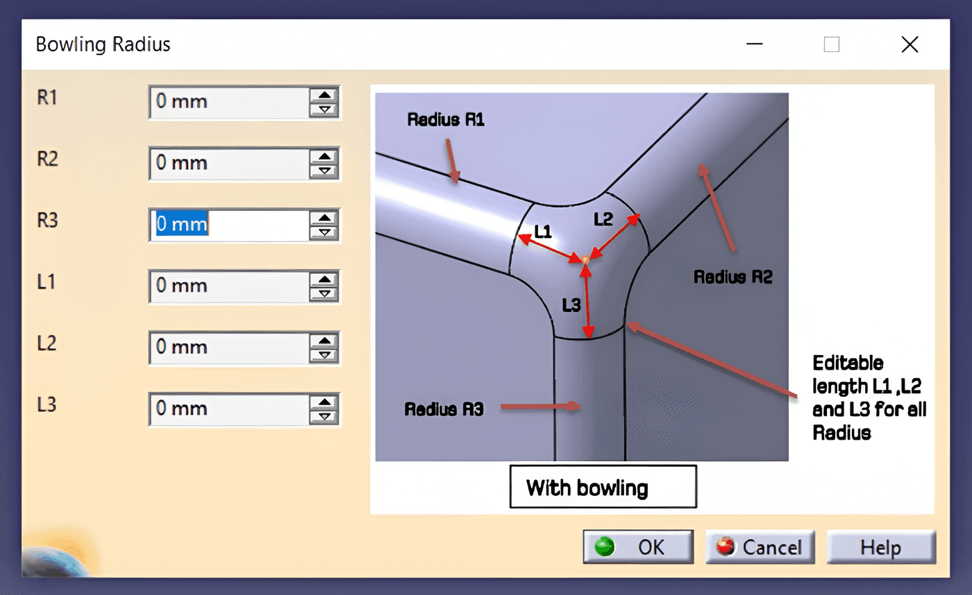
Creation Of Bowling Radius
Problem Statement: In BIW processes, creating precise bowling radii is critical for smooth surface transitions and maintaining structural integrity.
Solution: Using automated tooling with advanced control systems ensures accurate and consistent formation of bowling radii, resulting in smoother transitions and improved structural performance across parts.
Efficiency Improvement: This automation reduces rework by 12%, enhances surface quality, and shortens production time, leading to an overall efficiency boost of 10%.
Use case illustration

Use case illustration
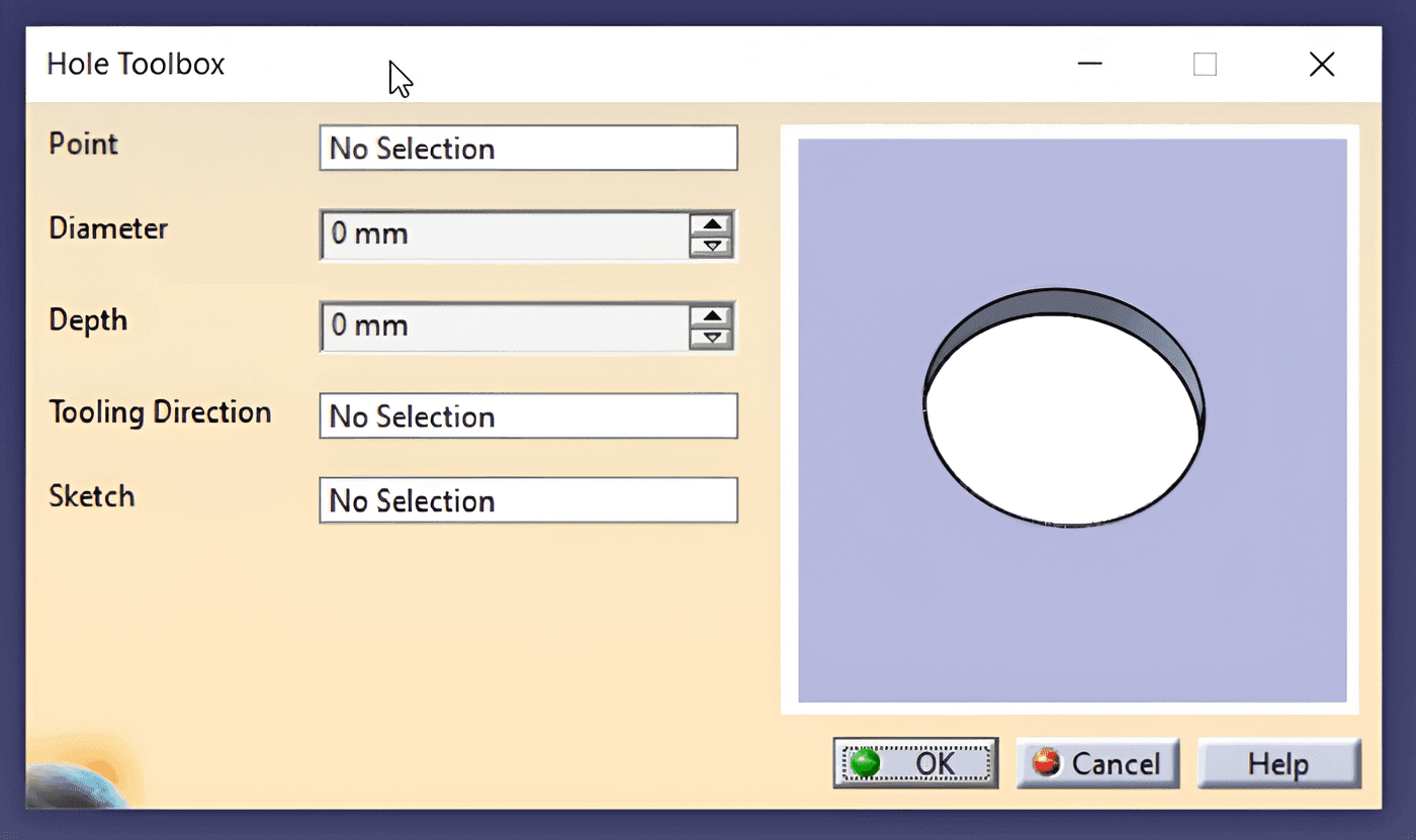
Creation Of Hole Feature
Problem Statement: In BIW manufacturing, the creation of hole features is essential for assembly and weight reduction. Traditional drilling methods can result in misalignment and burr formation, leading to assembly issues and increased rework.
Solution: Implementing automated drilling and machining techniques with precise positioning and control ensures consistent hole dimensions and locations, minimizing misalignment and enhancing assembly quality.
Efficiency Improvement: This approach can reduce rework rates by 15%, improve cycle times by 20%, and enhance overall production efficiency by ensuring higher accuracy and reducing material waste.

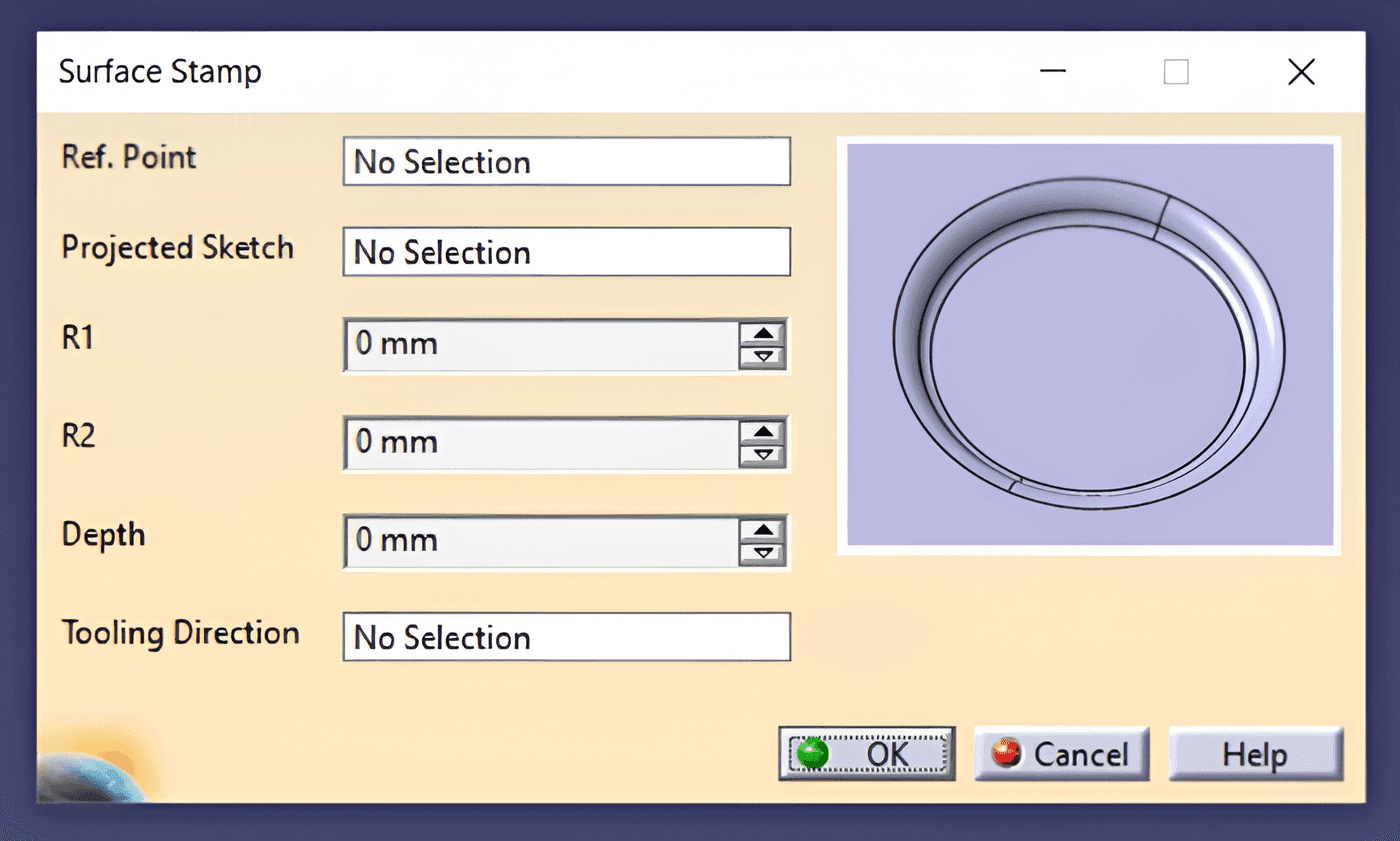
Creation Of Surface Stamp
Problem Statement: Creating surface stamps is essential for adding features such as textures or logos. Traditional stamping methods may result in inconsistent impressions, leading to aesthetic defects and compromised part integrity.
Solution: Utilizing automated surface stamping technology with precise control over pressure and timing ensures consistent impressions, enhancing the quality and appearance of the final product.
Efficiency Improvement: This automation reduces production defects by up to 20%, minimizes rework, and improves cycle times by 15%, ultimately enhancing overall efficiency and product quality.
Use case illustration

Use case illustration
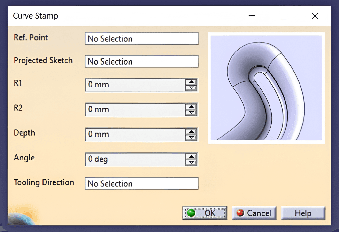
Creation Of Curve Stamp
Problem Statement: The creation of curve stamps is essential for achieving intricate designs and proper fitment of components. Traditional stamping methods may struggle with consistency, leading to distortion and uneven curves.
Solution: Implementing advanced curve stamping technology with precise control over curvature and pressure allows for accurate and uniform designs, improving both aesthetic and functional quality.
Efficiency Improvement: This approach can enhance production accuracy, reducing defects by 18% and shortening cycle times by 12%, resulting in improved overall efficiency and reduced rework costs.

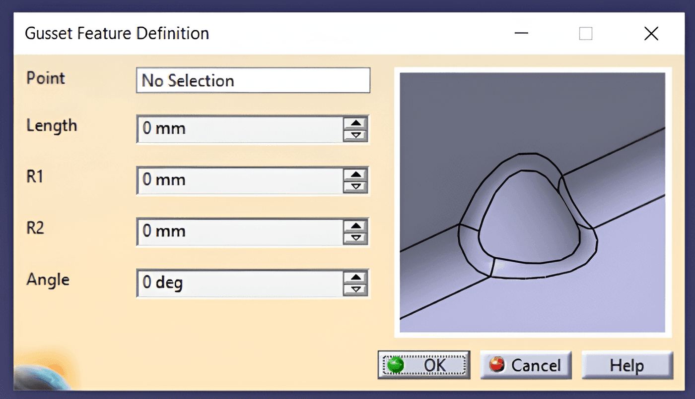
Creation Of Gussets
Problem Statement: Gussets are vital for providing additional strength and stability to structural joints. Traditional methods of creating gussets can lead to inconsistent shapes and sizes, compromising structural integrity of rework.
Solution: Utilizing automated gusset forming processes with precise measurements and control ensures uniformity in shape and size, enhancing the strength of joints and improving overall structural performance.
Efficiency Improvement: This automation can reduce rework by up to 15%, improve cycle times by 10%, and enhance overall production efficiency by ensuring consistent quality and reducing material waste.
Use case illustration

Use case illustration
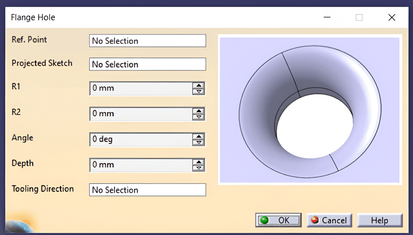
Creation Of Flanged Holes
Problem Statement: The creation of flanged holes is crucial for providing secure fastening points and enhancing structural integrity. Traditional methods may result in misaligned or poorly formed flanges, leading to assembly difficulties and increased rework.
Solution: Employing automated processes for flanged hole creation ensures precise alignment and consistent flange dimensions, improving the quality and reliability of fastened joints.
Efficiency Improvement: This method can reduce rework rates by 15%, enhance assembly speed, and improve overall production efficiency by approximately 12%.

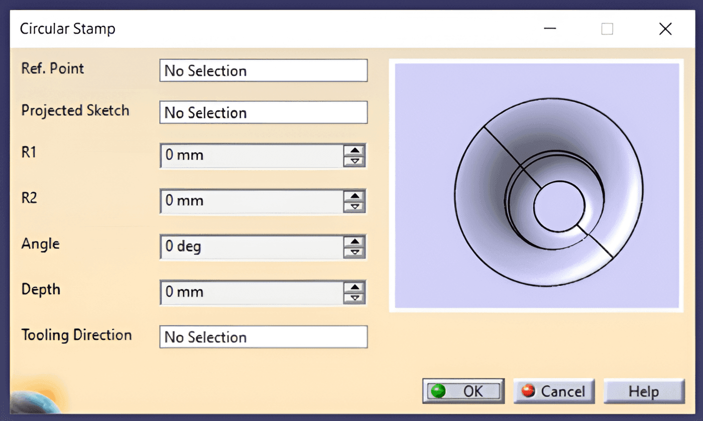
Creation Of Circular Stamp
Problem Statement: Creating circular stamps is essential for forming features like holes or decorative elements. Traditional stamping methods can lead to inconsistent dimensions and poor alignment, resulting in defects and assembly issues.
Solution: Implementing automated circular stamping techniques with precise control over force and position ensures uniformity in size and shape, improving the quality and functionality of stamped features.
Efficiency Improvement: This approach can reduce defect rates by 20%, decrease cycle times by 15%, and enhance overall production efficiency by ensuring consistent quality and minimizing rework.
Use case illustration

Use case illustration
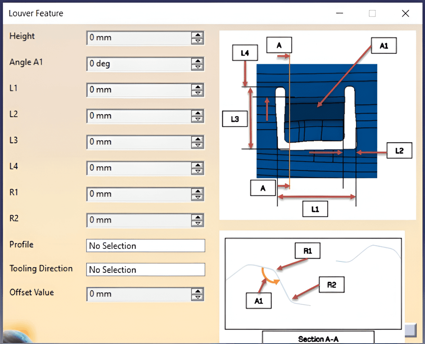
Creation Of Louver Feature
Problem Statement: The creation of louver features is crucial for enhancing ventilation and aesthetic appeal in vehicle components. Traditional methods often result in inconsistent louver shapes and sizes, leading to airflow issues and increased rework.
Solution: Utilizing automated louver forming technology with precise control over dimensions and angles ensures uniform louver features, optimizing both functionality and appearance.
Efficiency Improvement: This automation can reduce rework rates by up to 18%, improve cycle times by 12%, and enhance overall production efficiency by ensuring high-quality, consistent results with minimal material waste.

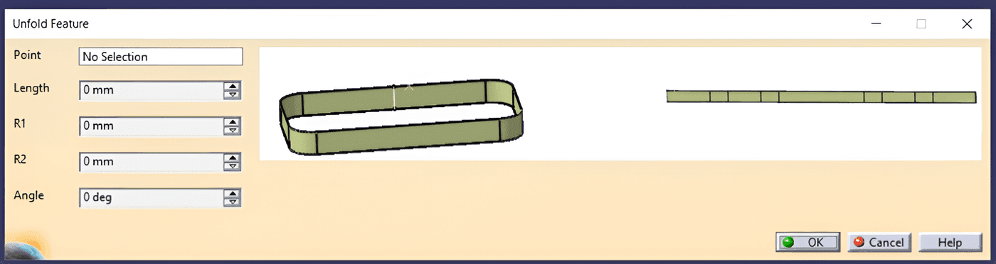
Creation Of Unfold Feature
Problem Statement: In BIW manufacturing, the creation of unfold features is essential for transforming complex 3D shapes into flat patterns for efficient cutting and assembly.
Solution: Implementing advanced CAD/CAM software for the unfold feature allows for precise calculation of flat patterns, ensuring accurate dimensions and facilitating smoother transitions from 3D to 2D layouts.
Efficiency Improvement: This approach can reduce material waste by up to 20%, enhance production speed by 15%, and minimize rework, resulting in improved overall efficiency and better utilization of resources.
Use case illustration

Use case illustration
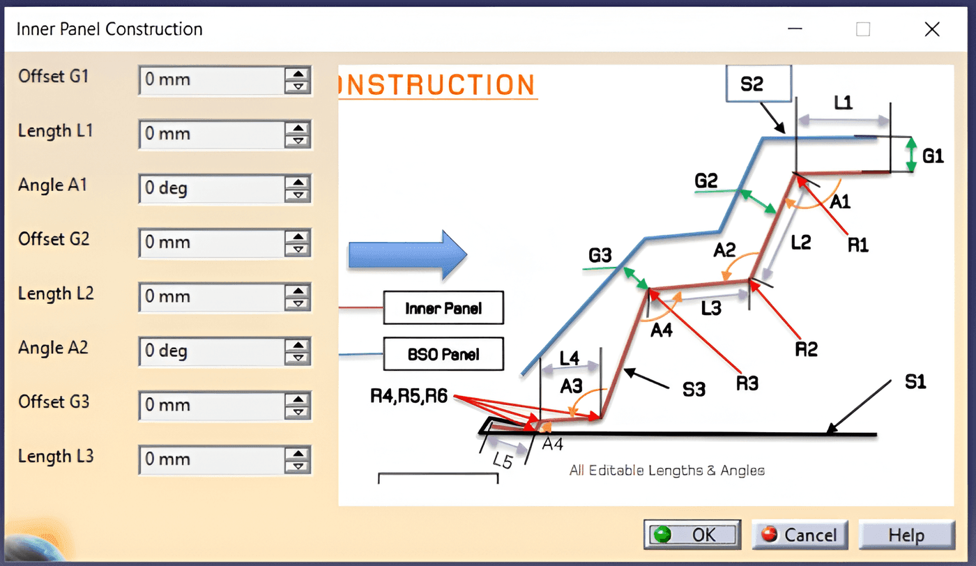
Inner Panel Flange Construction (Inner + BSO Panel) - 10 parameter
Problem Statement: Misaligned and inconsistent flanges during inner panel and BSO panel construction lead to poor joint strength and increased rework.
Solution: Automating flange construction with precise control improves alignment and consistency, enhancing joint quality and reducing defects.
Efficiency Improvement: This method reduces rework by 15% and improves production efficiency by 10%.

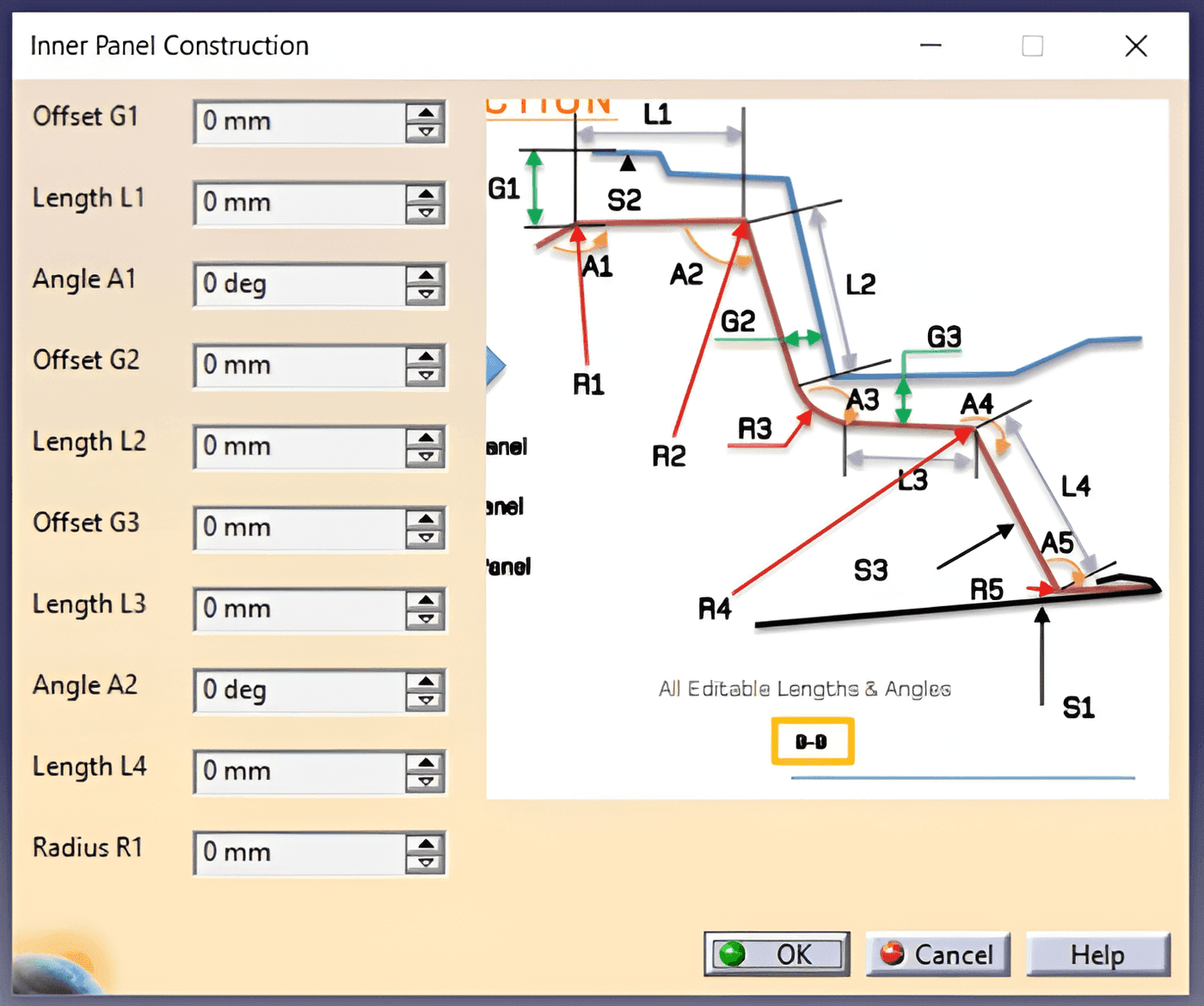
Inner Panel Flange Construction (Inner + Outer+ BSO Panel) - 15 parameter
Problem Statement: Inaccuracies in the flange construction of inner, outer, and BSO panels in BIW manufacturing often lead to assembly issues, improper sealing, and weakened structural integrity, causing rework and inefficiencies in the production process.
Solution: Automating the flange construction process with precise control over critical parameters ensures consistent and accurate flange formation, improving joint strength and reducing defects.
Efficiency Improvement: This method can reduce rework by up to 15% and improve overall production efficiency by 12%, resulting in stronger joints and better alignment of panels.
Use case illustration

Use case illustration
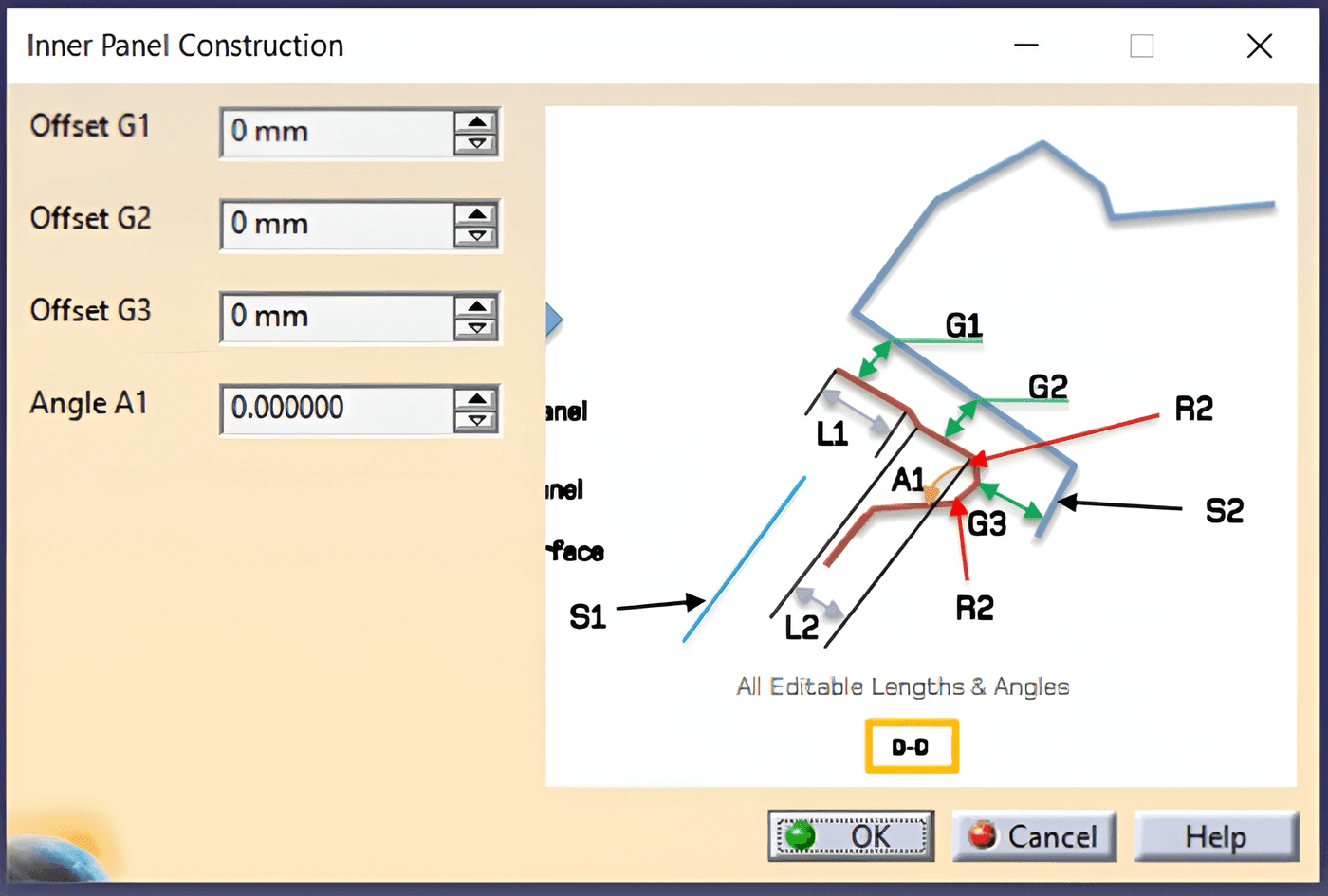
Inner Panel Flange Construction (Inner + BSO Panel) - 16 parameter
Problem Statement: Inconsistent flange construction between the inner panel and BSO panel can lead to poor fitment, compromised joint strength, and sealing issues, resulting in increased rework and assembly inefficiencies.
Solution: Implement automated flange forming with precise control over parameters such as flange height, angle, and width to ensure consistent, accurate flange construction for improved joint quality and sealing.
Efficiency Improvement: This approach reduces rework by 18%, enhances assembly efficiency, and improves sealing performance, leading to a 12% increase in overall production efficiency.

Inner Panel Frame Construction (Inner + BSO +Glass) - 6 Parameter
Problem Statement: Inaccurate inner panel frame construction, especially when integrating the BSO and glass, can lead to misalignment, poor fitment, and sealing issues, which compromise structural integrity and aesthetics.
Solution: Precise control over key parameters such as panel alignment, glass fitment, and frame strength ensures accurate construction, improving overall fitment and sealing quality.
Efficiency Improvement: This process reduces alignment issues by 15%, improves assembly efficiency, and reduces production time by 10%.
Use case illustration

Manufacturing and tooling automation

Automation does not stop at the design office. These are the tooling, mould and routing tasks we automate for manufacturing teams — the repetitive, geometry-heavy work that consumes engineering hours and quietly introduces errors.

Entry Surface Generation

Entry surfaces built straight from the trimline.

Building entry surfaces for mould and tool inserts by hand is repetitive and unforgiving — a wrong offset, an angle that drifts or a corner that does not match means starting again. This takes the dieface and trimline and generates the surface directly.

Insert surfaces that come out right the first time, on complex multi-curve trimlines as well as simple ones.

Entry surface generation shown across straight, curved and multi-curve trimlines

Scrap Cutter Body Automation

Upper scrap cutter geometry without the manual rebuild.

Designing the upper scrap cutter surface means repeated surface extraction and rotation steps, all needing precise scissor cutting alignment. Geometry mismatches and clearance errors are easy to introduce and slow to find.

Consistent cutter geometry with the alignment handled for you.

Four-step construction of an upper scrap cutter surface from the offset entry surface

Ejector Pin Placement

Pin layout driven by the geometry, not by hand.

Placing ejector pins manually risks uneven ejection, part bending and sticking, and interference that only shows up in production. This detects the flat, safe ejection areas, avoids ribs, bosses and cosmetic surfaces, and distributes the pins across them.

Balanced ejection and fewer surprises once the tool is cut.

Transparent mould base showing ejector pin placement through the plate stack

Tube and Hose Routing

Routing through crowded assemblies, automatically.

Routing metal tubes and hoses means picking start, end and support points, defining diameter, thickness and bend radius, working around neighbouring components, checking for clashes, then placing corrugated sections correctly. Every change means doing it again.

Routes that respect bend radius and clearance, and can be re-run when the packaging moves.

Metal tube route through an assembly with start, end and support points and a corrugated section marked

Wiring Harness Routing

Branches, clamps and bend radius handled together.

Manual harness routing in a complex assembly is hard to standardise between engineers. Branch management, bend radius limits, clamp spacing and interference checks all interact, and getting one wrong usually means reworking the rest.

Harness layouts that follow your rules consistently across variants.

Wiring harness route with branch points, supports and clip positions annotated

Flange and Bolt Pattern Automation

Hole patterns, threads and hardware in one step.

Semiconductor and vacuum tool design means creating flange bolt hole patterns, counterbores and threads, placing bolts, nuts and washers, holding pitch circle diameter and respecting edge distances — often across a great many holes in a single assembly. It is repetitive work where a wrong pitch or thread is easy to miss.

Standards-compliant patterns generated as a set rather than hole by hole.

Vacuum chamber assembly with multiple bolted flange interfaces

Parametric O-Ring Groove Design

Gland geometry to standard, every time.

O-ring grooves in vacuum flanges need precise width and depth, the correct compression ratio and standard-based gland design. Small dimensional errors leak, and a leak means rework and downtime. This generates the groove parametrically against the standard.

  • AS568
  • ISO

Sealing geometry you can trust across every flange in the assembly.

Grooved and non-grooved flange compared, with the O-ring gland section dimensioned

If your team repeats one of these tasks on every programme, it can almost certainly be automated.

Discuss your requirement

Frequently asked questions

Which CAD platforms do you automate?

We build automation and customization for CATIA, Siemens NX, PTC CREO, Autodesk and Solid Edge, including parametric design automation, automated drawing generation and CAD data migration.

How much design time does CAD automation actually save?

It depends on how repetitive the task is. Automating parametric design updates, drawing generation and standards checking typically removes the manual, repeatable portion of the work and reduces the rework caused by human error.

Can you integrate CAD automation with our PLM or ERP system?

Yes. We integrate CAD automation with PLM and ERP platforms including Windchill, Teamcenter, 3DEXPERIENCE and Enovia so that design data flows through to downstream systems without manual re-entry.

Sales specialists discussing a client's engineering requirement

Connect with our Sales Experts

Our dedicated sales team is ready to assist you in finding the perfect solutions tailored to your business needs. Whether you're looking for insights on our products or services, our experts provide personalized guidance to ensure a smooth, informed decision-making process. Collaborate with us to explore how we can drive growth, efficiency, and innovation together.